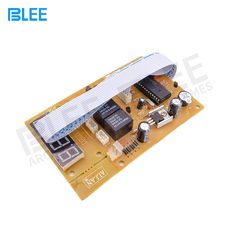
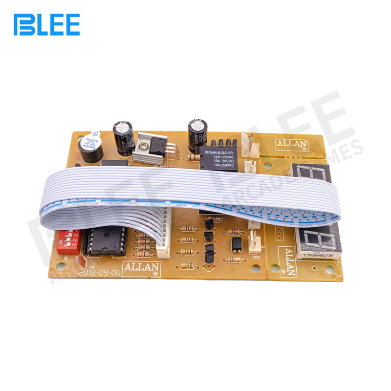
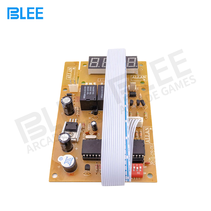
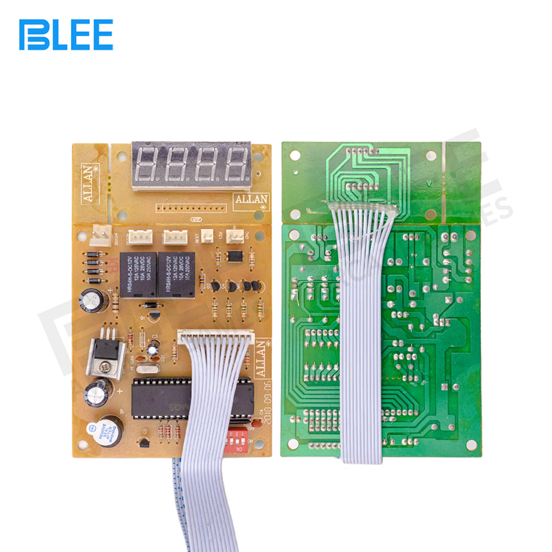
Timer Control Board Time Controller PCB Power Supply for Coin Acceptor Selector with 40cm White Lead,JY-15B
How it works?
Mode 1:Time runs down after receive signals-> Display shows remaining time and supply power to device-> it cuts off power after time runs out
Mode 2(Connect a button):Display shows remaining time after receive signals-> push button start-> time runs down and supply power to device-> it cuts off power after time runs out
Pause(connect a button): Push button pause: it cuts off power when pause, display shows remaining time. Re-supply power after push button pause again
Setting:
Please follow CODE ON DISPLAY and use button “S1” and “S2” to set up number
INPUT SIGNAL QUANTITY AND TIME
Please press button “S4”. B flashes. Please set up INPUT SIGNAL QUANTITY to active device (01-50).
Please press button “S4”, A flashes. Please set up TIME (01-99).
Please press button “S4”, B flashes. Please set up TIME (01-99).
Please press button “S4” 4 TIMES.
Please set up TIME for Warning Sound.
Please press button “S4” to finish.
GIVEN TIME:
Add time by free if input signals reach SETTING RATE during time is running.
Example Setting: input signal to active device: 01, input signals for given time: 03 give time: 02:10
Add time 02:10?? free if receive 3 signals during time is running.
Please press button “S4” 4 TIMES. B flashes. Please set up RATE OF INPUT SIGNAL QUANTITY.
Please press button “S4”, A flashes. Please set up GIVEN TIME.
Please press button “S4”, B flashes. Please set up GIVEN TIME.
Please press button “S4” to finish. Mode Setting
Please follow table to set up operating function:
Please hold on button “S1” and “S2” simultaneously for 3 seconds to get into MODE SETTING.
Please use button “S1” and button “S2” to set up number for CODE
Please press button “S4” to switch to next code

